


Rotary Seal Design Best Practices for Long Service Life
Understanding Rotary Seal Fundamentals and Service-Life Drivers
What defines a rotary seal and why longevity matters
Rotary seals (also called rotary shaft seals or oil seals) are components that retain lubricants and exclude contaminants on rotating shafts or interfaces. Service life is driven not just by the elastomer or PTFE lip, but by a system of interacting factors: material compatibility, shaft finish and runout, operating pressures, temperature cycles, lubrication regime, and installation. Designing for long life requires treating the seal as part of a mechanical system, not as an isolated part.
Key performance parameters to quantify at design stage
Before selecting a seal geometry or material, quantify these variables: rotational speed (rpm), shaft diameter, pressure differential across the seal, expected temperature range, working fluid chemistry, acceptable leakage rate, shaft surface roughness (Ra), radial runout limits, and momentary transients (pressure spikes, shock loads). Documenting these drives material choice, lip geometry and tolerance specifications.
Material Selection: Matching Chemistry, Temperature and Wear
How to choose elastomers and PTFE compounds
Material choice is the single biggest determinant of durability. Elastomers (NBR, FKM, EPDM, silicone, FFKM) offer elasticity and resilience; PTFE-based compounds (filled PTFE) offer low friction and high chemical resistance but require precise support or backup rings. Select based on fluid compatibility, operating temperature, and abrasion/corrosion expectations. For example, NBR (nitrile) is common for mineral oils up to ~120°C; FKM (Viton) for higher temperatures and aggressive fluids; FFKM for extreme chemical resistance. Filled PTFE (graphite, MoS₂, bronze) is used for high-speed, high-wear or where low friction is critical.
Comparative material properties (practical guidance)
Use the table below to compare commonly used materials and typical use cases. These ranges are industry-typical; always verify with supplier datasheets for specific compounds.
| Material | Typical Temp Range (°C) | Chemical Resistance | Wear & Friction | Typical Applications |
|---|---|---|---|---|
| NBR (Nitrile) | -40 to +120 | Good for mineral oils, fuels | Moderate wear, low cost | Hydraulic/pneumatic seals, oil seals |
| FKM (Viton) | -20 to +200 | Excellent for oils, fuels, many chemicals | Good wear resistance | High-temp hydraulic seals, automotive |
| FFKM (Perfluoroelastomer) | -20 to +250 | Outstanding chemical resistance | Good but expensive | Severe chemical environments, vacuum |
| Silicone | -60 to +200 | Poor for hydrocarbons, good for water/steam | Higher wear, low compression set | Temperature-critical, food grade |
| PTFE (filled) | -200 to +260 | Excellent broad chemical resistance | Very low friction; fillers improve wear | Rotary seals at high speed/temperature |
Sources for ranges: manufacturer datasheets, Parker O-Ring Handbook and ASTM/ISO guidance (see references).
Geometry, Shaft & Housing Tolerances, and Surface Finish
Shaft geometry and finish recommendations
Shaft diameter tolerances and surface finish (Ra) are critical. Recommended shaft surface roughness for most lip-type rotary seals is Ra 0.2–0.8 μm (8–32 μin), with hardness typically HRC 45–60 or 50–60 on some recommendations. Excessively rough surfaces increase abrasive wear; too-smooth surfaces can promote stick-slip for elastomer seals. Limit radial runout; typical design targets are runout less than 0.03 mm for precision rotary seals—adjust based on speed and seal type.
Seal housing and axial clearance
Design housing bores with correct interference or clearance depending on seal type. Radial seals often require interference fit in housing to prevent extrusion; back-up rings may be necessary under pressure. Ensure axial compression is controlled during installation—over-compression degrades seal lip life. Manufacture grooves and retaining features within specified tolerances to avoid seal distortion.
Dynamic Sealing Design: Lip Geometry, Springs, and Backup Elements
Lip profiles, spring tension and contact stress
Lip geometry controls contact pressure and leakage. For rotary applications, a balance is needed between adequate contact pressure (to exclude contaminants) and low friction (to reduce heat and wear). Single-lip seals with garter springs are common for oil retention; spring preload should be specified so that contact pressure is sufficient at operating temperature considering elastomer relaxation. Avoid excessive lip pressure which increases frictional heat and accelerates wear.
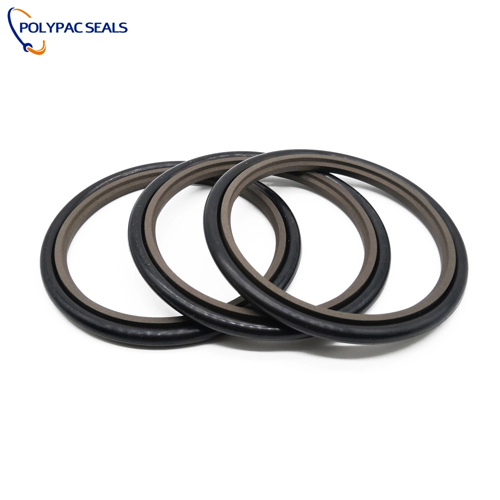
When to use backup rings, PTFE inserts or hydrodynamic features
For high pressure or reciprocating/rotary combined motion, backup rings prevent extrusion into clearance gaps. PTFE or filled-PTFE sliding elements reduce friction and are ideal for high-speed applications, but they must be supported by an elastomer energizer or metal case to maintain lip conformity. Hydrodynamic seals with engineered grooves can generate a lubricant film, reducing wear at higher speeds—consider these where leakage budgets allow.
Installation, Testing and Maintenance Practices
Best practices for installation to avoid initial damage
Proper installation reduces early failures. Key steps: inspect shaft/housing for burrs or gouges, use installation sleeves to protect lips, apply compatible lubricant to ease assembly, avoid twisting or overstretching elastomer seals, and torquing retaining hardware uniformly. Document installation records—date, operator, part batch—to support traceability and lifetime analysis.
Testing, run-in and preventative maintenance
Implement controlled run-in (break-in) procedures: start at low speed, monitor temperature and leakage, then ramp to target speed and load. Schedule oil analysis and visual inspections; track leakage trends. A predictive maintenance approach (vibration, thermography, oil particle count) helps identify impending seal failure before catastrophic loss. Typical planned replacement intervals should be derived from field data; conservative initial intervals (e.g., 6–12 months) while gathering operating data are recommended.
Common Failure Modes, Root Causes and Mitigations
Failure-mode table and actionable countermeasures
Below is a compact table of common seal failures, root causes and recommended mitigations to extend service life.
| Failure Mode | Root Cause | Mitigation |
|---|---|---|
| Abrasion / Lip wear | Contaminants; improper lubricant; rough shaft | Improve filtration; use low-abrasion material (PTFE, filled compounds); polish shaft |
| Hardening / Cracking | High temp or chemical attack; ozone/oxidation | Select high-temp/chemical-resistant elastomer (FKM/FFKM); use PTFE where needed |
| Extrusion | Excessive pressure; large groove clearance; soft material | Use backup rings; reduce clearance; increase material hardness or change design |
| Stick–slip / Vibration | Poor surface finish; incorrect lip preload; low speed | Optimize shaft Ra; adjust preload; use PTFE or low-friction compounds |
Advanced Considerations: Simulation, Custom Compounds and Validation
Use of FEA and tribology testing to predict life
Finite-element analysis (FEA) can model lip stresses, extrusion risk and temperature rise due to friction. Tribology benches and accelerated life tests provide empirical wear and leakage data which should be used to validate simulation results. Combining simulation with bench data reduces risk when deploying seals in novel or extreme environments.
Custom compounds and partnering with specialist manufacturers
Many applications benefit from custom elastomer formulations or PTFE compounds filled to optimize friction and wear. Working with an experienced seal manufacturer that can develop and test compounds shortens development cycles and improves long-term reliability.
Polypac: Custom Solutions and Manufacturing Capabilities
Who Polypac is — capabilities and R&D partnerships
Polypac is a scientific and technical hydraulic seal manufacturer and oil seal supplier specializing in seal production, sealing material development, and customized sealing solutions for special working conditions. Polypac's custom rubber ring and O-ring factory covers an area of more than 10,000 square meters, with a factory space of 8,000 square meters. Our production and testing equipment are among the most advanced in the industry. As one of the largest companies in China dedicated to the production and development of seals, we maintain long-term communication and cooperation with numerous universities and research institutions both domestically and internationally.
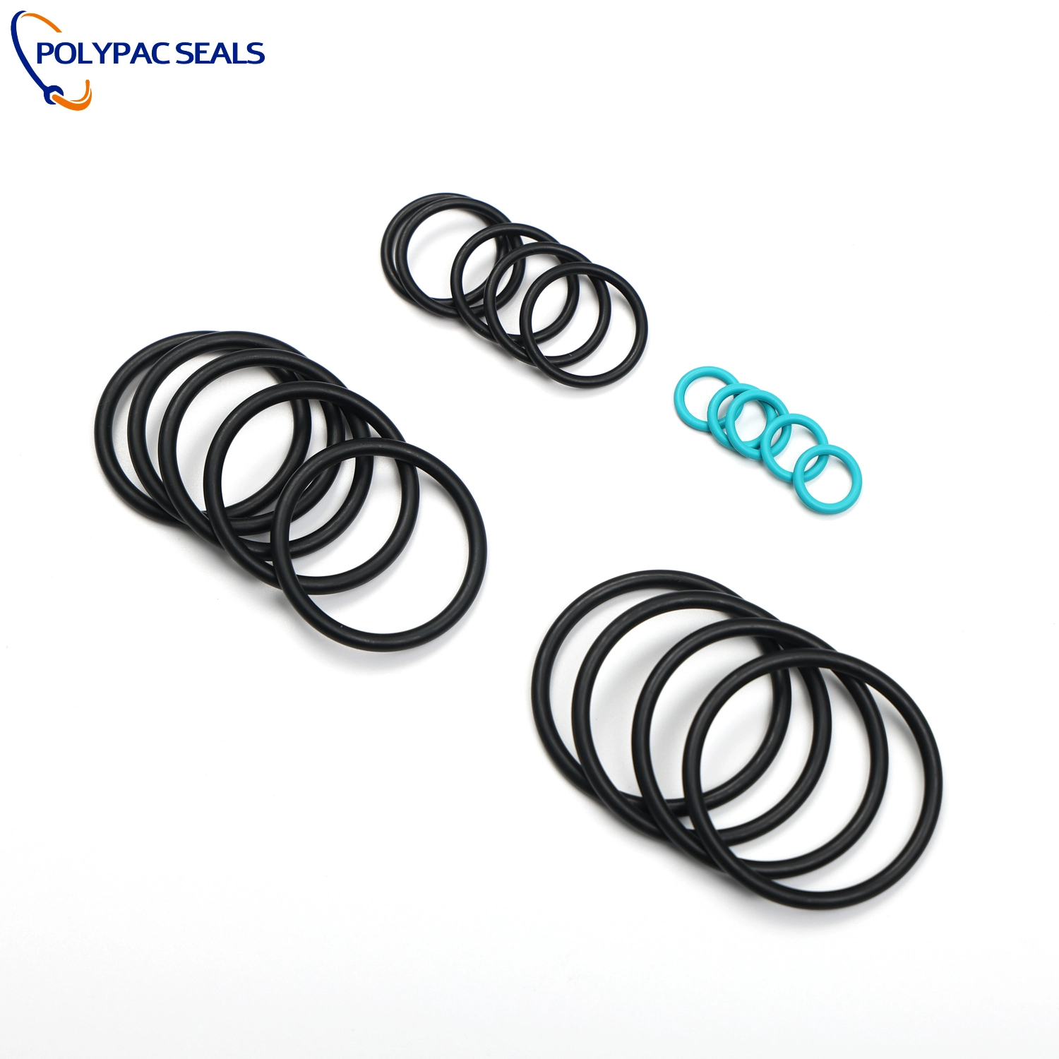
Product range, differentiators and technical strengths
Founded in 2008, Polypac began by manufacturing filled PTFE seals, including bronze-filled PTFE, carbon-filled PTFE, graphite PTFE, MoS₂-filled PTFE, and glass-filled PTFE. Today, we have expanded our product line to include O-rings made from various materials such as NBR, FKM, silicone, EPDM, and FFKM. Polypac offers a full portfolio including O-Rings, Rod Seals, Piston Seals, End Face Spring Seals, Scraper Seals, Rotary Seals, Back-up Rings, and Dust Rings. Our advantages include advanced compound development, high-capacity production, in-house testing, and collaborations with research institutions to support special working-condition solutions.
Polypac differentiates itself by:
- Specialized filled-PTFE expertise for high-speed and chemically challenging rotary sealing
- Large-scale custom rubber and O-ring production with strict process control
- Comprehensive testing facilities and partner-based R&D
For custom rotary seal projects requiring engineered lip geometry, unusual materials or accelerated validation, Polypac provides design support, prototyping and test validation services. Contact Polypac for consultations or to request samples and datasheets.
FAQ — Frequently Asked Questions
1. What is the typical service life of a rotary seal?
Service life varies widely by application: for general industrial oil-seals it may be 2–5 years; for severe environments or high-speed applications, life can be months to a year if improperly specified. Proper material selection, geometry, shaft finish and maintenance can extend life significantly. Use field data to set replacement intervals.
2. How do I choose between elastomer and PTFE rotary seals?
Choose elastomers (NBR, FKM) for flexibility, lower cost and good sealing with moderate temperatures. Use PTFE or filled-PTFE when you need low friction, wide chemical resistance, or high-temperature stability. Many designs combine a PTFE sliding element with an elastomer energizer.
3. What shaft surface finish and hardness are best for rotary seals?
Typical recommended shaft Ra is 0.2–0.8 µm (8–32 µin). Shaft hardness commonly recommended is >45 HRC for long wear life; verify with your seal supplier for the exact material and application.
4. When are backup rings necessary?
Use backup rings when extrusion is possible due to high pressure, large clearances, or soft sealing materials. Backup rings are essential for high-pressure hydraulic seals and where reversible motion or pulsation exists.
5. How should I approach installation to avoid early failures?
Inspect and prepare shaft/housing, use installation sleeves, lubricate with compatible fluid, avoid stretching or twisting seals, and validate seating. Keep records of installation and initial run-in measurements.
6. How can I validate a new rotary seal design before production?
Combine FEA to check stress/extrusion with tribology bench tests for wear and leakage. Perform accelerated life testing under expected extremes and confirm with a field pilot run.
Contact & Product CTA: For tailored rotary seal solutions, material guidance, or prototype orders, contact Polypac’s technical team to discuss your application, request samples, or view our product catalog (O-Rings, Rod Seals, Piston Seals, End Face Spring Seals, Scraper Seals, Rotary Seals, Back-up Rings, Dust Ring). Email or call for an application review and quotation.
References
- Parker O-Ring Handbook — Parker Hannifin. Accessed 2026-01-05. https://www.parker.com/literature/O-RingHandbook.pdf
- SKF: Shaft Seals Technical Guide. Accessed 2026-01-05. https://www.skf.com
- Polytetrafluoroethylene — Wikipedia. Accessed 2026-01-05. https://en.wikipedia.org/wiki/Polytetrafluoroethylene
- Hydraulic seal — Wikipedia. Accessed 2026-01-05. https://en.wikipedia.org/wiki/Hydraulic_seal
- O-ring — Wikipedia. Accessed 2026-01-05. https://en.wikipedia.org/wiki/O-ring

Pneumatic Seals: The Ultimate Guide to High-Efficiency, Low-Friction Sealing for Air Systems

PTFE Tubes: The Ultimate Guide to High-Performance, Chemically Inert Tubing Solutions

Scraper Seals: The Ultimate 2026 Guide to Selection, Types, and System Longevity

PTFE Oil Seals: The Definitive Guide to High-Performance Sealing for 2026

Gaskets: The Ultimate Guide to Types, Materials, and Selection for Industrial Sealing
Products
What does "AS568" mean?
How important is surface finish on the metal parts that contact the seal?
How do I choose the right material for my sealing application?
What is the difference between a static seal and a dynamic seal?
What is the difference between NBR and FKM materials?
Stay Updated with Industry Insights
Subscribe to our articles and receive the latest news, expert guidance, and technical updates directly in your E-mail.
Rest assured that your privacy is important to us, and all information provided will be handled with the utmost confidentiality.

Polypac is a trusted global supplier of high-performance sealing solutions, providing OEM & ODM services for industries worldwide.
E-mail:
Phone/WhatsApp:
© 2025 Polypac Seals. All Rights Reserved.
dms
DMS
DMS